I highly recommend the TPL - Tasks Parallel Library - 'DataFlow' library. It's a very good abstraction of the TPL itself, easy to use. I was in a situation where I had to parallelize the execution of a file-converter, which in a single instance-run used only 15% CPU. By parallelzing it I was able to utilize 100% CPU and finish the conversion-job much, much quicker.
IT works with .NET 4.5 and onwards, and I believe I saw a .NET Core version, too. But here's the .NET 4.5 version: https://www.nuget.org/packages/Microsoft.Tpl.Dataflow
Install with NuGet and look to the web for examples of use. Note that many of the examples deal with async-awaitable methods, but the library works quite well with synchronous tasks as well. I had no need for async use, so my inspiration-example below is synchronous tasks only:
public void ConvertFilesInFolder(string sourceFilesFolderPath)

{
string[] filePathsAndNames = getFilePathsAndNames(sourceFilesFolderPath);


// define a new 'ActionBlock', that you can push Tasks to.
var block = new ActionBlock(foobar =>
{
ConvertAndMoveTheFile(foo);
}, new ExecutionDataflowBlockOptions
{
MaxDegreeOfParallelism = 6 // 6 simultanous conversions (limit of my 3rd-party conversion library-licence)
});
// Go ahead and add conversion-Tasks to the action-block:
foreach (string filePathAndName in filePathsAndNames)
{
block.SendAsync(filePathAndName);
}
block.Complete(); // that's enough jobs...
block.Completion.Wait(); // ... now go ahead and execute until they're done. /* Note that as I set the max-degree-of-parallelism to 6, we're limited to this number of executed tasks at the same - parrallel - time. As soon as one task completes, another is retrieved from the action-block 'queque' */ }
public void ConvertAndMoveTheFile(string filePathAndName)
{
try
{
ConvertFile(filePathAndName);
moveOriginalFileToArchive(filePathAndName);
}
catch (Exception ex)
{
// log, but otherwise suppress and move to next.
}
}
I found this blog-post very helpful in getting introduced and started with the library.
I've just taken delivery of a couple of Arduino Pro Mini's and want to share how to program them, using the Arduino IDE and a FT232RL FTDI USB to TTL serial adapter.
The Arduino Pro Mini has the same feature-set as the Arduino Uno, for example, but is much, much smaller and doesn't consume the power the other Arduino's do, so it may be used in battery-powered projects or stuff where space is limited.
I'm told there's a 5v and a 3.3v version - I got the 5v ones.
Please refer to the below pictures for how to wire the units up. It's really quite easy, in as much as the pins on the FT232 corresponds exactly to the pins of the Arduino Pro Mini. So I'm simply using 6 female-to-female jumper cables, not even separated:
Remember to set the FT232 to 5v if you're programming the 5v version of the Pro Mini, and 3.3v if you have the 3.3v Pro mini. That's really the only thing that's possible to mess up! The 5v/3.3v setting is made by setting this jumper to its correct position (which should be marked on the board):
Note that the Arduino Pro Mini shouldn't be connected to its' own power source - the FT 232 will deliver the power for now. Now, as you connect the units together via the jumper cables, you may be surprised to note how the Arduino starts blinking red, and furthermore there's a strong red LED that's turned on. Don't be alarmed; at least with my version of the Pro Mini, the red LED simply signifies the unit is powered on, and the blinking red stems from the fact that the unit was pre-programmed with the standard 'blink' sketch - in which the on-board LED blinks once every second.
Fire up the Arduino IDE, and in the 'tools->boards' menu select the 'Arduino Pro or Pro mini' variant. Select the right COM-port and hit 'upload' - that's really should be it.
Raison d'être: I set out to write about the SOLID software development principles. Specifically, my aim was/is to make these things more understandable to other developers who, much in the way as yours truly, found it troublesome to have to decipher lengthy, complex articles and books on the matter. These principles are for everyone to learn and use, but I found that they were hard to fully grasp; quite possibly because I come from a non-English speaking background. So with this series of articles I'm setting out to try and de-mystify the principles, with only the best intentions in mind. The principles apply to many layers of software development. In my articles, I specifially aim to describe them as they relate to programming. I hope it'll be of use to you. Thank you for stopping by.
This will be a 5 article-series about SOLID. SOLID is all the rage; at least as far as the job-adds I'm reading are concerned; "you are expected to honor the SOLID principles" etc. So what exactly is SOLID about? Plain and simple, it's a set of guide-lines in developing object-oriented systems. They are a group of concepts that have proven themselves valuable for a great many people coding a great many pieces of software. A tale told by your elders in software engineering, if you will, that you will want to pay heed to so you can boast on your CV that you're into the SOLID principles - and you'll be a better developer for knowing them, I promise you that. Heck, you're a better developer for simply _wanting_ to know them!
[S]OLID - The Single Responsibility principle
The Single Responsibility is the first in the set of principles that make out the SOLID acronym. It states that a class should have only one single reason to change. And one reason only.
And why is this a good thing? Because the clutter from having a class do too much stuff is long-term damaging to whatever you're trying to design.
That distinction - "a single reason to change" - is important. The principle is not "a single thing to do"; a class may certainly perform one or more related tasks within the same scope of the class' responsibility. For example, a class which performs logging to a text-file and a database would not be considered breaking the single responsibility principle. If you were to add functionality to log to, say, a central systems management tool, that's not breaking the principle: that class is still only having one reason to change, and you have merely exercised that reason. But if you were to introduce functionality to send a notification on, say, the log-disc being close to full - that's breaking the principle: new stuff to do, unrelated to the primary responsibility.
Below is listed the primary risks involved in not following the principle, as well as the benefits of, well, following it. But first let's go about how to fulfill the principle. It's very simple, really: Go through your classes and look for those that perform two or more different actions. For example: do you have a class that renders an object AND saves it to disk? Not good - the class is clearly having more than 'one reason to change' - it might be a change in the rendering, or a change in the persistence to disc-functionality. Take the below example:
public class Logger { public Logger() { } public void WriteLog(string message) { // do something to write the message to disk log } public void GenerateLoggingStatistics() { // do something to retrieve some stats } }
... which finds us with a Logging-class that writes to a log-file and is capable of generating some logging statistics as well. I'm not familiar with any form of tooling which may aide in this kind of 'single-context search', unfortunately. All I can offer is this, that you'll likely be looking to keeping your classes short. Big classes - my personal, general rule of thumb is 200 lines - marks a danger-sign that the class has too much on its plate. Further to that point, It's not necessarily a danger-sign that you have a multitude of small classes as opposed to a few heavy ones - likely quite the opposite. Keep'em short and lean. In regards to how to facility future changes without breaking the principle, look to hide implementation by interfacing, and there's also the magnificent strategy-pattern to be utilized.
That's it - that's the single responsibility principle, the first of the five. Not so terribly difficult, but then again that's the beauty of the principles, that they're easy to learn but difficult to master. I best saw the adverse of applying the principle described as a 'swiss army-knife class'; if you keep that image in your mind as you traverse your own, you're bound to avoid ending up with exactly those kind of 'do-all' classes. And as an extra positive, classes that are lean and mean are per definition easier to test, easier to read, easier to maintain. And that's what the Single Responsibility principle is all about.
Hope this helps you in your further career. And good luck with it, too!
Further to my post on programming a standalone ESP8266-12, this post describes how to actually run the ESP when it's been programmed. Specifically, how to wake it up from deep sleep.
Disclaimer: This post describes the bare neccessities for making the unit run. For production purposes it may be necessary to pull other pins high/low, add capacitors for smoothing out currents, so on and so forth. I came across this post, which suggested the following: "A large capacitor (suggest using 470 uF) across the Vcc to Gnd rails on your breadboard or PCB is a vital ingredient that will minimize reset inducing voltage fluctuations. A 0.1 uF decoupling capacitor across the ESP8266 Vcc to Gnd inputs very close to the pins (within 1/2 inch). DO NOT SKIP THIS COMPONENT! This cheap yet often overlooked component, when missing, is the root cause of ESP8266 resets."]
Pre-requisites! I'll be using these components:
@ A standard ESP8266-12 on a breakout-board such as the one shown.
@ Two 4.7k resistors.
@ A 3v battery (I use a CR123a) for powering the ESP826612.
The following requirements should be met:
@ All connections, including those on the The ESP 8266-12 on the breakout-board, are solid and conduct power as they should.
@ The battery holds at least 2.8v of power.
@ The ESP8266-12 has been programmed with the following sketch:
// Time to sleep (in seconds):
const int sleepTimeS = 5; // 5 seconds

void setup() {

  delay(2000);                      // Wait for two seconds
  ESP.deepSleep(sleepTimeS * 1000000);
}

// there's nothing in the loop section - all's done in the setup() section.
void loop() {
}
Given the above is in order, go ahead and connect the components as per the following pictures:
- The RESET and GPIO16 pins should be connected - this enables the ESP 8266-12 to wake up from deep sleep mode.
- The GPIO0 and GPIO2 should be connected to VCC with a 4.7k resistor in the middle. This is to prevent a so-called 'zombie-mode', in which the ESP8266-12 has trouble waking up from deep sleep.
With the ESP connected like so, my ESP8266-12 happily resets/wakes up, does nothing for two seconds, then sleeps again for five seconds before repeating the cycle.
If you look to the tiny blue LED situated just below the ESP and the antenna, you will notice it blinking every ~ 7 seconds, to indicate when the ESP comes back to life.
I measure 15 microampere (uA) when in deep sleep. This will keep the unit running for a months on end.
The ESP 8266-12 won't last long on a batteries; it uses 80 mA per hour. So to use it for last-lasting battery-powered sensors it's necessary to put it in sleep mode and, furthermore, use a stand-alone version without all the development board components. So this post will be about how to program a stand-alone ESP 8266-12.
Pre-requisites! I'll be using these components:
@ A standard ESP8266-12 on a breakout-board such as the one shown.
@ A FT232RL USB to TTL serial adapter, for programming.
@ A 3v battery (I use a CR123a) for powering the ESP826612.
@ The Arduino IDE - I'm using version 1.6.12 for this tutorial.
The following requirements should be met:
@ The FT232RL is recognized by the PC and shows as a virtual COM port.
@ All connections, including those on the The ESP 8266-12 on the breakout-board, are solid and conduct power as they should.
@ The battery holds at least 2.8v of power.
@ The ESP core-libraries have been imported into the Arduino IDE.
Connect the components as per the following pictures:
It's important that the GPIO 0 pin is connected to ground - that's the signal to the ESP8266-12 that it's about to be programmed. I have found it's also important to power the ESP off and then on again before programming it from the Arduino IDE.
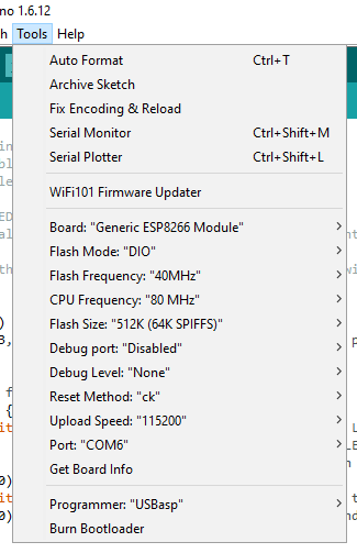
Having connected the above, we can move to the Arduino IDE. From the ESP-examples - File=>Examples=>ESP - load a basic sketch. Now head to the 'Tools' menu and ensure the below settings:
Again, remember to do a power-cycle of the ESP 8266-12 before programming it.
Given the above, it should be a simple matter of hitting 'Upload' and the Arduino IDE should program - 'flash' - the ESP8266-12.
Please note that the above it what works for me. Your USB-to-TTL module may be different, your PC may need a different upload speed, so on and so forth. You'll need to experiment a bit - as did I - if the above doesn't work straight away.
In a further blog-post I'll then document how to run the ESP - including bringing it in and out of deep sleep - after having programmed it.