Updating a GridView based on values changed in a DetailsView, but not finding the changes reflected in the GridView?
In the DetailView's ItemUpdated-method, make sure you have the the GridView.DataBind(), and make sure that in your Page_Load the initial databind, if any, is wrapped in an 'if (! Page.isPostBack)' clause. Which I didn't have, for specific reasons yet preventing the GridView update.
Hope this helps some-/anyone.
mandag den 25. marts 2013
onsdag den 6. marts 2013
Arduino: How to wire a relay
Here's my quick tutorial on how to hook up a relay to an Arduino; specifically a electromagnet switch relay from Omron, the G5SB-14.
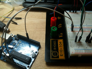
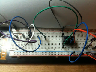
Here's a breadboard-look of how it's hooked up:
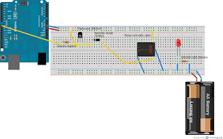
You'll see the Arduino on the left hand side, providing power to the relay and the accompanying components, and on the right hand side is the red LED I'm powering via it's own battery (you could, if you like, power the LED by the Arduino).
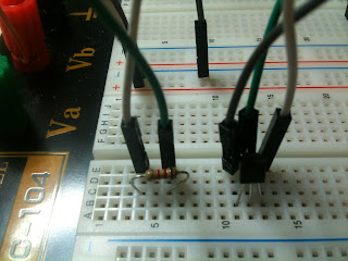
First off, we'll use the Arduino's digital pin 8 to send a signal to the relay, through the other components. So hook up the pin 8 to a 1 kohm resistor. Why the resistor, because the transistor I'm using that will catch the signal from the pin no. 8 can't handle the full 5v voltage from the digital pin.
Next, the transistor. Why use one? Because we can't operate the relay by the signal from the digital pin alone - it hasn't enough juice to switch the relay's internal magnetic switch. So hook up the transistor as per the image, with 1) the center pin - the base - hooked up to the digital pin via the resistor, 2) with the emitter - the left side of the transistor, when you're looking at the flat side of the component - hooked up to ground and 3) the collector - the right side of the transistor - going to the rectifier.
What's a rectifier? Well, it's a diode that guards the curcuitry from electrical flow from the relay when it's switched off, and a sudden change in current flow surges from the relay. To the relay it's like a night-club bouncer preventing the rush of current from entering the delicate transistor and Arduino - like "You behave, you relay, or I'll rectify your ass", so to speak. It's like a one-way street for current. If you're just messing around and reproducing this or a different example, you can go without it, but at your own peril.
Hook up the rectifier (in series) to one end of the relay coil, and hook the other end of the coil to power. It really is a coil inside the relay: Powering the coil creates a magnetic field inside the relay, 'creates' a magnet if you will, that attracts a metal pin inside the relay enclosure, which in turn touches one of two tiny contacts (on and off) and creates a connection between them.
That's the Arduino part of the tutorial. Now we need something for the relay to actually turn on and off. In this case, a red LED, powered by the battery. Hook up the battery, the LED as shown in the picture (don't forget the resistor unless you're willing to sacrifice an LED or two on the alter of trial-and-error), and connect the relay.
In connecting the relay, hook up the relay's 'common' pin to ground. This pin is the one that holds on to one end of the metal pin which is to touch either contact - labelled normally on (NO) and normally closed (NC). Refer to the data sheet of your specific relay to make sure it's hooked up correctly - it's not always such that these labels - NO, NC and COM (for Common) are written on the relay itself.
The way the relay is used, is thus: if you want the relay to turn something off when signalling it from the Arduino, you must connect your application's power source - in this case the battery for our LED - to the normally opened (NO) pin. If on the other hand you want to use the relay to turn something on, you must connect the power source to the normally closed (NC) pin.
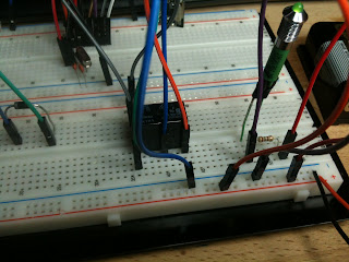
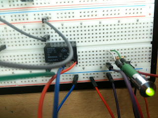
The below pictures show the orientation of the pins on the Omron relay that's used here, the
G5SB-14:

If you hook up the example-breadboard, you should be able to do what did I: Play an Arduino sketch which turns the relay on and off every 5 seconds. Here's the example code:
That's it - that's how you hook up a relay to the Arduino. Happy switching on and off!
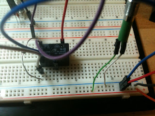
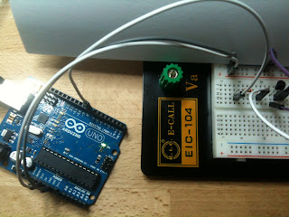
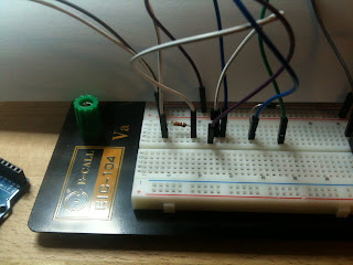
I'm including a bunch of pictures below, of how I've set it up on my breadboard. Hopefully the pictures might be helpful.


You can use the relay that's referred to with AC voltage, i.e. to turn on and off mains-powered applications such as lamps and such, BUT DO THIS ONLY ONLY ONLY if you're very confident in your abilities and take your safety seriously. AC POWER KILLS if you are not careful.
Here's a breadboard-look of how it's hooked up:

You'll see the Arduino on the left hand side, providing power to the relay and the accompanying components, and on the right hand side is the red LED I'm powering via it's own battery (you could, if you like, power the LED by the Arduino).
First off, we'll use the Arduino's digital pin 8 to send a signal to the relay, through the other components. So hook up the pin 8 to a 1 kohm resistor. Why the resistor, because the transistor I'm using that will catch the signal from the pin no. 8 can't handle the full 5v voltage from the digital pin.
Next, the transistor. Why use one? Because we can't operate the relay by the signal from the digital pin alone - it hasn't enough juice to switch the relay's internal magnetic switch. So hook up the transistor as per the image, with 1) the center pin - the base - hooked up to the digital pin via the resistor, 2) with the emitter - the left side of the transistor, when you're looking at the flat side of the component - hooked up to ground and 3) the collector - the right side of the transistor - going to the rectifier.
What's a rectifier? Well, it's a diode that guards the curcuitry from electrical flow from the relay when it's switched off, and a sudden change in current flow surges from the relay. To the relay it's like a night-club bouncer preventing the rush of current from entering the delicate transistor and Arduino - like "You behave, you relay, or I'll rectify your ass", so to speak. It's like a one-way street for current. If you're just messing around and reproducing this or a different example, you can go without it, but at your own peril.
Hook up the rectifier (in series) to one end of the relay coil, and hook the other end of the coil to power. It really is a coil inside the relay: Powering the coil creates a magnetic field inside the relay, 'creates' a magnet if you will, that attracts a metal pin inside the relay enclosure, which in turn touches one of two tiny contacts (on and off) and creates a connection between them.
That's the Arduino part of the tutorial. Now we need something for the relay to actually turn on and off. In this case, a red LED, powered by the battery. Hook up the battery, the LED as shown in the picture (don't forget the resistor unless you're willing to sacrifice an LED or two on the alter of trial-and-error), and connect the relay.
In connecting the relay, hook up the relay's 'common' pin to ground. This pin is the one that holds on to one end of the metal pin which is to touch either contact - labelled normally on (NO) and normally closed (NC). Refer to the data sheet of your specific relay to make sure it's hooked up correctly - it's not always such that these labels - NO, NC and COM (for Common) are written on the relay itself.
The way the relay is used, is thus: if you want the relay to turn something off when signalling it from the Arduino, you must connect your application's power source - in this case the battery for our LED - to the normally opened (NO) pin. If on the other hand you want to use the relay to turn something on, you must connect the power source to the normally closed (NC) pin.
The below pictures show the orientation of the pins on the Omron relay that's used here, the
G5SB-14:

If you hook up the example-breadboard, you should be able to do what did I: Play an Arduino sketch which turns the relay on and off every 5 seconds. Here's the example code:
// connect digital pin 8 to the transistor, via a resistor

int led = 8;


// the setup routine runs once when you press reset:

void setup() {

// initialize the digital pin as an output.

pinMode(led, OUTPUT);

}


// the loop routine runs over and over again forever:

void loop() {


delay(5000);               // wait for 5 seconds

digitalWrite(led, HIGH);   // turn the relay off

delay(5000);               // wait for a second

digitalWrite(led, LOW);    // turn the relay on

}
That's it - that's how you hook up a relay to the Arduino. Happy switching on and off!
I'm including a bunch of pictures below, of how I've set it up on my breadboard. Hopefully the pictures might be helpful.


Abonner på:
Opslag (Atom)